The purpose of this series is to bring a fuller understanding of the
major components of Top Fuel Dragsters and Funny Cars with an insider’s
perspective. We will touch on many items in detail and how the
components and various systems are interrelated along with a few side
notes and an occasional story along the way.
The list of subjects covered will be vast and detailed to the degree
necessary for the above average fan and simple enough for the average
fan to come away with a better appreciation of the intricacies of the
modern “Nitro” car.
Today’s lesson focuses on the Fuel Management Systems, the various components and how it all works.
This Special Series Gives You The Insides and Outs of Nitro Racing from the Technical Side …
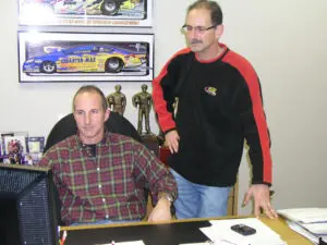
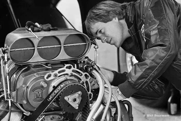
Mike Kloeber is certainly one of the most talented tuners to ever crew chief a nitro car.

He began working in the nitro ranks during his teenage years, spinning the wrenches for champions such as Gary Beck, Jeb Allen and the Candies-Hughes team, just to name a few.
Kloeber earned his first crew chief job in 1986 when the legendary Don “Snake” Prudhomme hired him away from Tom “Mongoose” McEwen.
He took a break from racing in 1990 to pursue an education in aeronautical engineering and was content to pursue a job in another field until he assisted Len Seroka in returning to Top Fuel.
The sport might have been on the sidelines for Kloeber, but a few trips to the track provided all the proof that he needed to confirm the passion still burned in his heart for drag racing.
Kloeber joined on with Jim Epler and tuned his Funny Car to the sport’s first 300-mph Funny Car run.
Of all the accolades he gained along the way, few could compare with the six IHRA Top Fuel world championships he earned alongside of Clay Millican, a driver with whom he tuned from his first ride in 1999 up until 2007.
He’s since enjoyed stints with Bob Tasca III and Kenny Bernstein Racing.
Kloeber accepts his latest drag racing role, an opportunity which provides the challenge of educating the above average drag racing fan with the intricacy involved in maintaining and tuning a Top Fuel dragster.
UNIVERSITY SYLLABUS
The purpose of this series is to bring a fuller understanding of the major components of Top Fuel Dragsters and Funny Cars with an insider’s perspective. We will touch on many items in detail and how the components and various systems are interrelated along with a few side notes and an occasional story along the way.
The list of subjects covered will be vast and detailed to the degree necessary for the above average fan and simple enough for the average fan to come away with a better appreciation of the intricacies of the modern “Nitro” car.
a d v e r t i s e m e n t
Click to visit our sponsor’s website
GETTING STARTED –FUEL MANAGEMENT
The primary function of the fuel system is to deliver a metered amount of fuel at idle and wide open throttle. The relatively short time  you use part throttle isn’t a significant concern since the work the engine is doing is greatly diminished during the burn out. The Pump volume, nozzle area are what determine the total output of a given set-up. Compression ratio, camshaft profile and blower overdrive determine the actual volume requirement. Clutch application is the major determining factor in the rate of enrichment. This is an over simplified scenario but you should get the idea.
THE COMPONENTS
THE PUMPS – In the late 70’s most of the cars used a Crower, Hilborn or Enderle fuel pump. The fuel systems were very simple with most cars running an Enderle barrel valve with a single -8 line from the pump to the barrel valve. These pumps would have been in the 12 to 20 GPM range depending on whether Dale Emery had zoomed up your Enderle pump. To increase pump output an overdrive was used between the cam and pump drive.
Fast forwarding to the current TF and FC pumps, the output is upwards of 95 GPM with some just over 100 GPM.
The preferred pump is the spur gear style.
Along the way the gerotor pump was reliably used successfully by a number of teams. Dave Settles was behind these pumps and they are generally referred to as the ‘Nuke’. When cast iron pump housings became available the reliability and linearity of the spur gear pump became the preference. Most of us are familiar with the gerotor being used as an oil pump in Chrysler products and the spur gear pump being used in Chevys and other brands.
I used the gerotor pump during the time I ran Clay Millican because of the pumps durability and reliability. You could run a spoon through it and it will still run low E.T. With me being the rare exception the rest of the teams use pumps made by Sid Waterman (Drag Racing Hall of Famer) or Mike Kopchick of Rage Fuel Systems.
In the pump world Sid is the main man. Sid’s has been a crew chief, engine builder and parts manufacturer for decades and has made many contributions to drag racing and enjoys the lions share of the business in TF and FC racing. Sid has expanded his business to Sprint Car racing, Indy cars and NASCAR. I used to wonder why Sid moved from Southern California to a place that can’t even be pronounced, Gualala, CA. After my first visit to Sid’s house I had my answer. When you are in Sid and Judy’s living room and you look out the enormous window you only see one thing, Pacific Ocean. It is the most spectacular view I have ever seen (I like the ocean).
Mike Kopchick’s pump is a very reliable part and it is very similar to Waterman’s using a larger diameter spur gear to achieve the desired output while maintaining a simple and dependable design. Even though I consider Sid a good friend I have been using the ‘Rage” pump the past couple of years since I stopped using the ‘Nuke’. I must admit I really miss my ‘Nuke’. The phone calls to Settles regarding its lack of required maintence were generally priceless.
a d v e r t i s e m e n t
Click to visit our sponsor’s website
METERING VALVES (BARREL VALVE) – Today all cars use a Pete Jackson ‘Metering Valve’ (that’s what Pete called them) J.T. Stewart, in  Phoenix, makes them and has for several years. Most people will know Pete Jackson from his famous gear drive business in Burbank, CA. Those of us who have had the fortune and pleasure to have worked with Pete were left with an indelible impression and a thorough education.
Pete Jackson was quite a character. I will never forget one particular encounter with Pete. I was working at Prudhomme’s before I was crew chief. We had been having trouble in ’88 getting the car to run as good as it should. So ‘Snake’ called Pete and asked him to come over to the shop and take a look at what we were doing. When Pete came in the back door he was wearing his white lab coat. Pete really liked cheap stinky cigars and he stood in front of the car and looked at the fuel system for a few minutes quietly and then said. “You know what the first rule of the fuel systems is? Don’t confuse the fuel. How do you know where all the fuel is going you got too many lines here? One line in and one line out, that’s all you need,” Pete looked at the fuel flow number of the pumps we were using and came back the next week with a new duplex metering valve, idle check valves and a nozzle sheet. It wasn’t long after that the car started to run pretty good.
The duplex metering valve replaced the two barrel valve system most teams were using. The need for two barrel valves was due to the fact the old Enderle style barrel valves were too small to flow the volume from two pumps being overdriven, I don’t remember who used two barrel valves first. It was probable Dale Armstrong. Back then Dale was the most innovative guy in the pits. It was often said that Bernstein could raise money faster than Armstrong could figure out ways to spend it.
Pete Jackson continued to improve the metering valve for years by moving and adding idle return ports over the years. Today the Metering Valve is largely unchanged and it comes from J.T. Stewart in a -10 or a -12 inlet size. Stewart makes a number of specialty items for the clutch, fuel system J.T.’s parts are used by most of the TF and FC teams.
SLIDE VALVE – I get lots of questions about what is a Slide Valve and how does it work. It’s a relatively simple item that can be  difficult to explain. Beyond the pump and the Metering Valve, the Slide Valve is the single most important part of the fuel system. The Slide Valve is responsible for the fuel curve and the rate of enrichment.
AFT Slide Valve: The AFT was the first Slide Valve to my knowledge. I’ll try to keep this simple. A piston that has a slot or opening to allow fuel to pass through at idle slowly closes over time based on applying air pressure to the sealed area on top of the piston. There is a speed control to allow the piston to move slowly at first then faster toward the end of the travel to accommodate the rate of enrichment requirement. A timer starts the movement of the piston and another timer to speed the piston when desired. Every tuner has a slightly different approach to the clutch application and basic tune-up philosophy. So no two teams run exactly the same set-up with regard to bypass flow (return flow) and speed of the slide valve.
Pete Jackson Slide Valve: After a conversation I had with Pete explaining to him how the AFT Slide worked, I asked if we could come up with a way for the fuel control device to work off fuel pressure rather than adding more timers and having to control the speed of the Slide Valve. He was on it big time. I was putting the Cristen Powell Sequent/Royal Purple team together at the end of ’96 and before we ran in Phoenix, before the ’97 season, Pete had made the first 5 from a sand cast pattern he made himself. The last time I was at his shop before Pomona this year the pattern was leaning against the wall with his other sand patterns. I still have the first two he made and used them for many years. It is a marvelous invention with only 1 moving part. Today they are most prominently used and manufactured by Alan Johnson. They’re on over ½ of the top ten cars in TF and FC.
The Pete Jackson Slide Valve works by supplying fuel pressure to a chamber with a 2.5 in. piston connected to a .750 diameter stem with a notch cut to bypass fuel at idle. When you hit the throttle the fuel that is supplied to the chamber is shut off and the pump pressure pushes the piston that pulls the stem slowly past the inlet hole to close the fuel bypass off over time. The chamber that was full of fuel at idle is passed through what is called the time jet. The bigger the jet size the faster the Slide Valve moves and conversely slower with a smaller jet. The stem of the Slide Valve is where the magic is. You actual cut a curve in the stem to create the fuel curve. Each stem is cut for the pump size, total nozzle area and system pressure. I would add there are a few more ways to tailor the way it works with inlet size, and the depth of the notch in the stem. I personally have made almost 2000 runs with only two malfunctions. Both of those were user errors. One was a stuck seal (I put a Slide Valve on the car after sitting in the drawer for a couple of years) and the other a piece of junk in the line that plugged the time jet. There are few parts that can be that reliable.
Jet style fuel management: For many years we all used an Enderle screw in jet style management to bleed off fuel in the beginning of the run. The John Force/Austin Coil combination was probably the last of the top teams to use air timers to open and close valves to control the fuel curve. I’ve looked in Coil’s management box and it was full of more timers and air line than you could imagine. I used to say that Jets don’t lie. It was easy to add or take away fuel by simply changing the jet or the timer. I guess it worked pretty good for Coil, he won a dozen or more championships that way.
BDK FUEL PRESSURE REGULATOR – This indispensable device was created by Don Jackson Engineering. Jackson (No relation to Pete) has tried to change the name to a DJE valve but everybody still calls it by its original name. It works like a big poppet valve. The pressure is set with an externally adjustable spring. CO2 is added to the top of the poppet to prevent the regulator from opening before it’s intended time. The BDK can regulate 15 to 20 GPM at 500 to 700 psi. Most teams open the BDK around 3 seconds into the run. The BDK eliminates any need for other top end lean-out devices. If you lube it occasionally you won’t have any trouble with it at all. It’s a really good part.
a d v e r t i s e m e n t
Click to visit our sponsor’s website
FLOW METERS – Most teams use a main flow meter and a return flow meter. The main flow meter is placed just past the Metering Valve before the distribution block that divides the fuel to the intake manifold, injector hat and cylinder heads. The return flow meter is place either between the pump and the fuel management or at the end of the fuel management before it returns to the inlet of the pump or the fuel tank. The flow meter has a tiny impeller in a precision tube. A proximity sensor counts the rpm of the impeller and the Racepak system displays the flow. The flow is typically displayed on the Racepak dash and is a critical component of the tune-up while idling and backing up from the burnout. The last adjustment you see crew chiefs make just before staging is to raise the idle speed and increase the idle flow.
INJECTOR HAT – There are two basic styles with the Injector Hat. There is a 2, 3 or 4 butterfly style or the Barn Door type. Personal preference is the major determining factor. The FC is limited in height by rules and more appropriately the driver’s vision. The dragsters are also limited in height because they would probably raise them up another foot or two if there weren’t any rules. You have to remember that drag racing is sometimes a game of mine is taller than yours. In some of the injector hats there is more inside than just an empty space. Some have guide vanes and fins to direct the air into the supercharger and others are, as you might assume, just empty. Over all you want the injector hat to be a simple but functional part of the car. Its primary function is to get the air to the supercharger. Some small gains can be had with guide vanes and such but I would remind you that the races are won or lost with the clutch. Personally, on the dragster I prefer the Gibson Miller because of its robustness. I’ve broken a couple of Metering Valves off the tall carbon hats and it gets a little expensive when that happens. At one time they were the tallest of the group but Waa ambulance came to the rescue and the carbon hats were allowed to be as tall and as such have become effectively taller then the Gibson-Miller. Either way I have run 4.40’s with the Gibson-Miller so height by itself really isn’t that important.
NOZZLES – The Nozzle system is very straight forward. Most teams use a 3 nozzle per cylinder system. One nozzle is in the manifold and two in the heads that are commonly referred to as the ‘down’ nozzles. The idle nozzle will either be in the manifold or one of the down nozzles. It doesn’t really matter where idle nozzles are. They work about the same either way. Two of the three nozzles will have what are called Ball Checks in them. A ball check is a ball at the end of a spring that closes off the fuel flow up to about 25 or 30 psi. The spring looks like a glorified heavy duty ball point pen spring. This keeps only the fuel from the supercharger and the idle nozzle flowing into the cylinder. The blower has a somewhat chaotic air flow and each cylinder needs a slightly different amount of fuel. All the teams use metering jets (Drop-ins) made by Kenny Crawford that are made to the exacting demands of the racing community. Each metering jet has a chamfered approach and a precision hole. You need a couple hundred of them to keep all of your heads nozzle’d and a good selection in the drawer.
AUXILLIARY NOZZLES – Many teams use an extra set of nozzles to tune finicky cylinders or to reduce the fuel pressure as the engine is rising in RPM. My favorite term for the Auxiliary’s is what Johnny West calls them, ‘Turbo Nozzles’. If you have a cylinder that likes to go out on the starting line or early in the run you can put a smaller jet in that cylinder and then open another (Auxiliary) later in the run to keep from hurting the piston.
AJ VALVE – The AJ valve is a clever device to increase the throttle response of the fuel system. When it’s in the closed position all the fuel goes in to the engine or through the idle bypass circuit. (Idle check valves) This device has several counterparts made by a few different guys, J.T. Stewart makes one operating on a pendulum valve principal. Bill Miller uses a giant check valve. But most teams use an AJ valve made by Alan Johnson. It looks and works very similar to a BDK valve. A small -3 fuel line is run from the pump to the bottom of the piston (poppet) to crack open the valve from its closed position allowing fuel to then move unrestricted through the fuel management. The pressure is set with an externally adjustable spring (like the BDK) the more pressure it takes to open the AJ valve the more fuel goes into the engine at the crack of the throttle. The reason you would need one of these devices is due to the fact that 45% to 55% of the pumps output is returned to the tank when you hit the throttle. For example to keep the math simple; say you have a 100 GPM pump and you want 55 GPM going into the engine at the step of the throttle. You would be sending almost ½ of the fuel back to the tank. That makes for a fairly lazy throttle response. Can you hear the driver complaining that when they hit the throttle nothing happens? Well unfortunately that is somewhat true. There are a few ways to make the response better by running very high idle check pressures or running the engine at very high idle flow.
a d v e r t i s e m e n t
Click to visit our sponsor’s website
HOW THIS ALL COMES TOGETHER
The engine is started and the driver turns the fuel pump on all the way then trims the fuel flow to the desired burnout idle flow. The driver then rolls through the water and does the burnout. When the car comes to a stop after the burnout the driver will take note of the engine idle speed and fuel flow. If necessary the driver can make the appropriate adjustment, most of the time no adjustment is necessary. When all the other pre-run rituals are completed, the driver is motioned to stop just short of the pre-stage beam. The crew chiefs will make sure each car is ready then the final adjustments to the idle speed and idle flow are done. The drivers are motioned that the car is ready and all theirs.
At the step of the throttle, fuel management is in the full lean position returning fuel to the tank (or recirculating fuel to the inlet of the pump in most cases) and as the car goes down the track the engine gets richer. The engine will get to the full rich condition around 2 seconds into the run. The clutch will finish applying around 3 seconds and the fuel regulator timer will let the CO2 off the BDK valve and the fuel will be regulated to the pre-determined pressure and flow.
Most cars will leave the starting line around 56 to 60 GPM and finish the run between 74 to 78 GPM.
In conclusion I would like to dedicate this particular segment to my dear friend Pete Jackson who passed away on May 19th. His wonderful and colorful personality will be missed by many. Pete’s contribution to drag racing and LSR is legendary, but largely overlooked. Myself and several of my contemporary’s are much better at their chosen profession because Pete was a very good teacher. Pete was never to busy to “rap about it” and he helped lots of guys make their cars “run like a rocket”. Pete really was a “Rocket Scientist”. I will miss him and I’m indebted for all the lessons I learned from him.

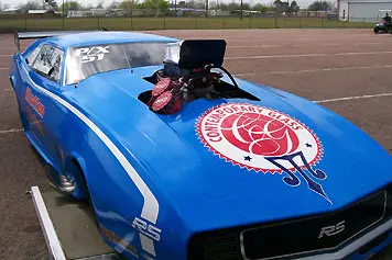
In this view the fuel comes from the pump to through the hexagonal shaped flow meter up through the AJ valve into the Pete Jackson Slide Valve. The BDK regulator is fed from the blue ‘T’ into the bottom of the BDK. You can see all the return fuel must pass through the Return Flow Meter first.